USB
Contents
Предназначение
Проектира се с цел да замени различни бавни интерфейси за предаване на данни, като паралелен, сериен, PS/2 с обща шина, към която могат да се включват всички тези устройства ползващи споменатите интерфейси.
USB интерфейсът има за цел и да улесни разработката на драйвери за нови периферни устройства.
Основни предимства:
- Автоматичнo конфигуриране (Plug and Play);
- Динамична инициализация (hot plug);
- Поддръжка на различни скорости и типове данни.
- 127 адреса за устройства.
- Не се изисква захрахнване (при малки мощности). USB интерфейсът включва захранваща линия с номинална стойност 5V. Може да предоставя до 500mA (2.0) и 900mA(3.0)
- Надеждност - изискванията за хардуер (приемници, кабели) и протоколите (драйвери) осигуряват интерфейс защитен електрически смущения от грешки при предаване. Ако има грешки те се откриват и коригират на хардуерно ниво.
Ограничения
- Разстояние 6 * 5м = 30м (including RS-232, RS-485, IEEE-1394b,
and Ethernet, allow much longer cables.)
- няма peer-to-peer ( частично решение USB OTG (On-The-Go)
- няма broadcasting
История
- usb1 Revision 1.0 was released in January 1996.
Windows 95 SE, Windows 98
- usb1.1 Повправка 1.1 (Септември 1998) добавя трансфер на данни (interrupt OUT).
- usb2.0 - Април 2000
- OTG on-the-go 2001
- usb3 - Ноември 2008, Windows 7
USB архитектура
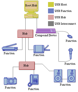
Дизайнът на USB архитектурата е асиметричен с топология тип звезда с максимум 7 нива. Топологията е изградена от три елемента: един хост, връзки, устройства (host, interconnects, devices).
От своя страна устройствата са хъбове и функции (функционалности)(hubs and functions).
Управление
- Управлението на USB системата се извършва единствено от хоста, към който е включен root hub-a (основният хъб). Посредством маркери (token) USB хоста уведомява кога някое устройство може да предава данни.
- Данните се предават на пакети разположени в логически канали (pipes), между хост и крайна точка (endpoint).
- Eдна и повече крайни точки се обединяват в логически интерфейс на едно устройство. Операционната система комуникира с това логическо устройство.
Адресиране:
- Формат - [Адрес на устройството][Адрес на крайна точка (endpoint)][Посока].
- Възможните адреси са от 0 - 127. Адрес 0 се използва за конфигуриране при начално включване на устройството
- Възможните крайни точки са от 0 - 15. Крайна точка 0 се използва за управление.
- Възможните посоки са IN и OUT. IN - от устройството към хоста, OUT - от хост към устройството.
- Едно физическо устройство може е много функционално (принтер+скенер, камера+микрофон, безжична мишка и клавиатура). Има два вида свързване на многофункионалните устройства:
- Устройството има вграден хъб и всяка функция се адресира поотделно. (compound device)
- Едно устройство има няколко логически интерфейса, с различни крайни точки. (composite device)
Устройствата не комуникират директно чрез прекъсвания с компютъра. Операционната система избира с кой да комуникира посредством хост контролер. Хост контролерът използва хардуерни прекъсвания. Хост контролерът периодично запитва всяко устройство и проверява дали то иска да комуникира с компютъра. Запитването може да е веднъж на всеки (микро) интервал или за HID устройства би могло да е на всеки 10 интервала (100Hz). Обикновено пакета за запитване е с размер 20 бита (4 PacketID + 7 device address + 4 end point address + 5 bit CRC). USB устройство не може да започне предаване на данни без да е запитано от хост контролера. Пакети предназначени и изпратени за устройство съдържат адрес на устройството и краен адрес (endpoint, pipe). 127 са възможните адреси, които могат да бъдат дадени от един хост контролер
Конфигурация, интерфейси и крайни точки
Всяко устройство може да има различни конфигурации. В момента на включване се определя каква конфигурация ще се ползва.
- Две различни конфигурации: устройството ползва ток от системната шина, същото устройство може да ползва външно захранване.
- Само една конфигурация може да е активна в даден момент
Всяка конфигурация има крайна точка за управление и един или повече интерфейси
- Всеки интерфейс има една или повече крайни точки за вход (OUT) и/или изход (IN).
- Интерфейсите работят последователно в споделена среда.
USB Скорости
Максимална скорост
USB устройствата могат да поддържат следните скорости на шината.
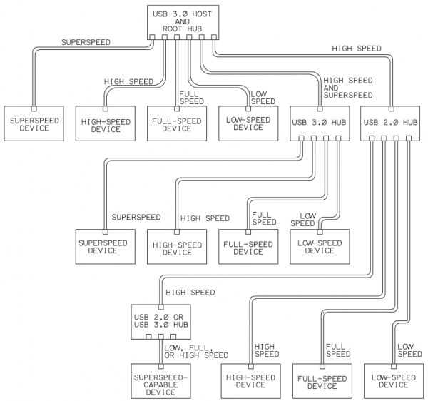
- Super Speed 5Gb/s v3
- High speed 480Mb/s v2
- Full speed 12Mb/s v1
- Low speed 1.5Mb/s v1
Реалната максимална скорост на предаване данни е между 10 и 20% по-ниска, поради резервираност на ресурсите и трафик за управление.
Логически канали
Логическите канали могат да ползват четири видa трансфер.
- Контролен (control) - За управление
- Постоянен (isochronous) - канал с гарантирана скорост за предаване в реално време (видео, звук). Възможна загуба на данни, защото няма проверки за грешки. Поради гарантираната скорост се резервира честотна лента и броят на тези канали е ограничен от капацитета на usb контролера.
- Прекъсваем (interrupt) - канал гарантиращ малко времезакъснение на устройства с малък трафик (мишки, клавиатури).
- Обемен (bulk) - Канал за предаване на голям обем от данни (файлове), използващ всичкия останал капацитет на USB връзката, без загуби на данни (но няма гарантирана скорост).
| Вид връзка | Control | Bulk | Interrupt | Isochronouse |
|---|---|---|---|---|
| Употреба | идентификация и конфигуриране | Принтер, скенер, памет | Мишка, клавиатура | Видео, аудио стрийминг |
| Подръжка | задължителна | не задължителна | не задължителна | не задължителна |
| Корекция грешки | да | да | да | не |
| Гарантирана скорост | не | не | не | да |
| Гарантирано време закъснение | не | не | да | да |
Класове устройства
Според своето предназначение устройсвата се разделята на следните класове:
- HID: Human Interface Device
- мишка, клавиатура, джойстик ...
- CDC: Communication Device Class
- модеми Ethernet, ISDN ...
- MSC: Mass storege class
- флаш памети, твърди дискове ...
Устройствата попадащи в точно определен клас, могат да се управляват от операционната система без да има нужда от допълнително инсталиране на драйвер
| Class | Usage | Description | Examples, or exception |
|---|---|---|---|
| 00h | Device | Unspecified | Device class is unspecified, interface descriptors are used to determine needed drivers |
| 01h | Interface | Audio | Speaker, microphone, sound card, MIDI |
| 02h | Both | Communications and CDC Control | Modem, Ethernet adapter, Wi-Fi adapter |
| 03h | Interface | Human interface device (HID) | Keyboard, mouse, joystick |
| 05h | Interface | Physical Interface Device (PID) | Force feedback joystick |
| 06h | Interface | Image | Webcam, scanner |
| 07 | Interface | Printer | Laser printer, inkjet printer, CNC machine |
| 08h | Interface | Mass storage | USB flash drive, memory card reader, digital audio player, digital camera, external drive |
| 09h | Device | USB hub | Full bandwidth hub |
| 0Ah | Interface | CDC-Data | Used together with class 02h: communications and CDC control |
| 0Bh | Interface | Smart Card | USB smart card reader |
| 0Dh | Interface | Content security | Fingerprint reader |
| 0Eh | Interface | Video | Webcam |
| 0Fh | Interface | Personal Healthcare | Pulse monitor (watch) |
| DCh | Both | Diagnostic Device | USB compliance testing device |
| E0h | Interface | Wireless Controller | Bluetooth adapter, Microsoft RNDIS |
| EFh | Both | Miscellaneous | ActiveSync device |
| FEh | Interface | Application-specific | IrDA Bridge, Test & Measurement Class (USBTMC), USB DFU (Direct Firmware update) |
| FFh | Both | Vendor-specific | Indicates that a device needs vendor specific drivers |
USB устройствата се програмират, така че да отговарят на един от класовете
Формат на данните
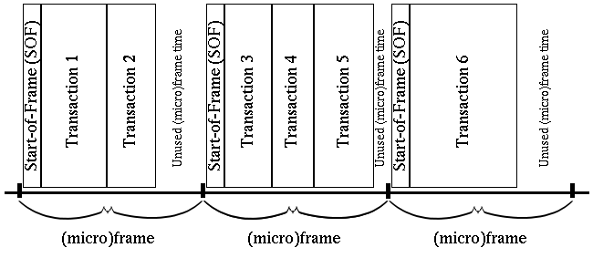
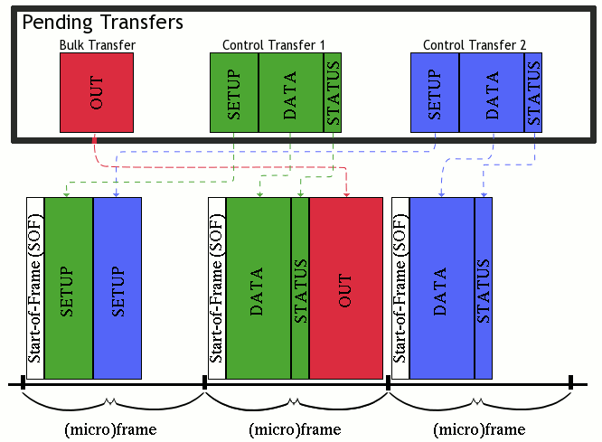
Текущата информация, която иска да изпрати определено устройство се нарича трансфер (transfer). Данните от един трансфер се разпределят в транзакции (фиг. ). Транзакциите се групират във фреймове(фиг. ), като транзакции от различни трансфери могат да се изпращат в различни фреймове(фиг.6). Един фрейм е с дължина 1ms. При High speed, всеки фрейм се разделя на 8 микрофрейма (по 125us). Всяка транзакция се състои от няколко пакета. Пакет (packet) най-малката информационна единица е пакет.
Основни понятия:
Всеки пакет съдържа:
- (задължително) описание на типа на пакета (PID - packet identification)
- (почти винаги) проверка за грешки (CRC)
- за token пакет - адрес и крайна точка
- за payload (data) пакет - данни
|
Transfer
Type
|
Max
Packet Size
|
||
|
LS
|
FS
|
HS
|
|
| Control |
8
|
8,
16, 32, 64
|
64
|
| Bulk |
-
|
8,
16, 32, 64
|
512
|
| Interrupt |
up
to 8
|
up
to 64
|
up
to 1024
|
| Isochronous |
-
|
up
to 1023
|
up
to1024
|
Най-често транзакцията включва:
- Token пакета изпратен от хоста.
- Устройството, което е описано в token пакета трябва веднага след получаването да изпрати своите данни.
- Потвърждение за получените данни.
- В началото на всеки фрейм се изпраща SOF транзакция, която служи за синхронизация. Транзакцията може да се състои от един (само при SOF start of Frame), два или три пакета се (фиг 4).
- Пакетите могат да бъдат с различна дължина в зависимост скоростта, вида на логическия канал и избраната конфигурацията (Т.3)
Сигнализация
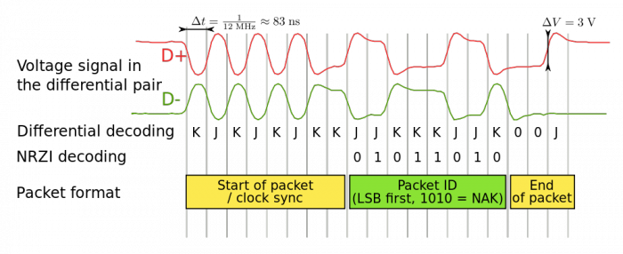
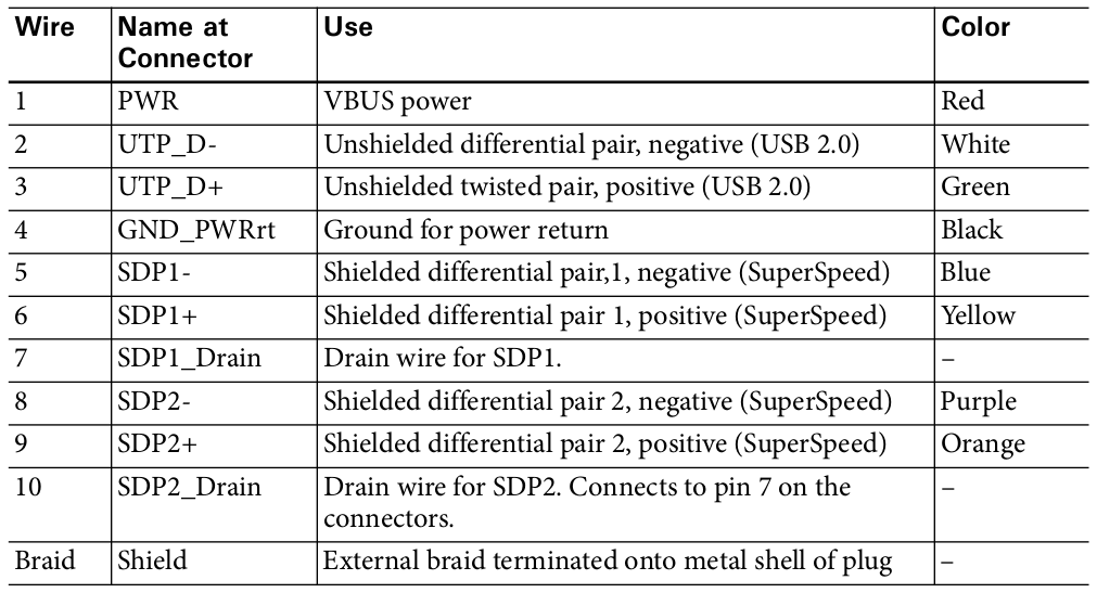
USB2 системата използва четири проводника. Два от тях се използват за обмен на данни с диференциални сигнали. Другите два USB кабела включват напрежение с номинална стойност Ucc = 5V и маса, което позволява да се захранват външни устройства. Двете информационни жила са усукана двойка, а захранващите може и да са от друг тип.
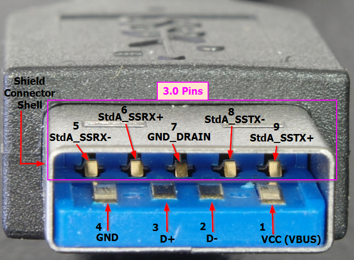
Всеки проводник в USB кабела има специфичен цвят. Сигналите за данни формират усукана двойка от бял (-Data) и зелен (+Data) цвят. За захранващото 5V напрежение се използва червен цвят. Общият сигнал (Ground) е черен (табл. 2.14).
| Сигнал | Цвят |
|---|---|
| +Data | зелен |
| -Data | бял |
| +Ucc | червен |
| Ground | черен |
USB 3
USB 3 надгражда USB стандарта. Добавят се две нови двойки физически линии за всяка посока, като А куплунга остава с непроменена форма, за да има обратна съвместимост с USB2. USB 3 позволява по голяма консумация на USB3 устройствата и може да сам да поеме инициатива за предаване на данни.
Задача
Bus 006 Device 009: ID 046d:c018 Logitech, Inc. Optical Wheel Mouse
Device Descriptor:
  bLength                18
  bDescriptorType         1
  bcdUSB               2.00
  bDeviceClass            0 (Defined at Interface level)
  bDeviceSubClass         0
  bDeviceProtocol         0
  bMaxPacketSize0         8
  idVendor           0x046d Logitech, Inc.
  idProduct          0xc018 Optical Wheel Mouse
  bcdDevice           43.01
  iManufacturer           1 Logitech
  iProduct                2 USB Optical Mouse
  iSerial                 0
  bNumConfigurations      1
  Configuration Descriptor:
    bLength                 9
    bDescriptorType         2
    wTotalLength           34
    bNumInterfaces          1
    bConfigurationValue     1
    iConfiguration          0
    bmAttributes         0xa0
      (Bus Powered)
      Remote Wakeup
    MaxPower              100mA
    Interface Descriptor:
      bLength                 9
      bDescriptorType         4
      bInterfaceNumber        0
      bAlternateSetting       0
      bNumEndpoints           1
      bInterfaceClass         3 Human Interface Device
      bInterfaceSubClass      1 Boot Interface Subclass
      bInterfaceProtocol      2 Mouse
      iInterface              0
        HID Device Descriptor:
          bLength                 9
          bDescriptorType        33
          bcdHID               1.11
          bCountryCode            0 Not supported
          bNumDescriptors         1
          bDescriptorType        34 Report
          wDescriptorLength      52
         Report Descriptors:
           ** UNAVAILABLE **
      Endpoint Descriptor:
        bLength                 7
        bDescriptorType         5
        bEndpointAddress     0x81  EP 1 IN
        bmAttributes            3
          Transfer Type            Interrupt
          Synch Type               None
          Usage Type               Data
        wMaxPacketSize     0x0005  1x 5 bytes
        bInterval              10
Device Status:     0x0000
  (Bus Powered)
Проводници и захранване на USB
USB <= 2
- 4 проводника
- Два проводника за захранване +/- 5V
- Няма проводник за тактова честота
- Предаването е асинхронно
- Останалите два проводника са за предаване на данни
- Обикновено се използва диференциално предаване
- Възможно захранване до 100mA
- При конфигуриране до 500mA
USB <= 3
Стъпки на свързване
- Attached
- Powered - подаване на захранване към устройството
- Default - Устройството се захранва и се достъпва на адрес 0, след като отговори му се изпраща адрес
- Address - Устройството е получило адрес от хост контролера по стандартния конфигурационен канал (Zero endpoint), който винаги е достъпен, независимо дали има конфигуриран адрес или не.
- Configured - Хост контролера е получил възможните конфигурации на устройството и е избрал една.
- Suspended - Ако няма трафик на данни за повече от 1 милисекунда. Режим на ниска консумация. Устройството излиза от този режим след наличие на активност по шината за данни.
1. The system has a new device. A user attaches a device to a USB port, or the
system powers up with a device attached. The port may be on the root hub at
the host or on a hub that connects downstream from the host. The hub pro-
vides power to the port, and the device is in the Powered state. The device can
draw up to 100 mA from the bus.
2. The hub detects the device. The hub monitors the voltages on the signal
lines (D+ and D-) at each of its ports. The hub has a pull-down resistor of
www.zshareall.com
91Chapter 4
14.25k–24.8k Ω on each line. A device has a pull-up resistor of 900–1575 Ω on
D+ for a full-speed device or D- for a low-speed device. High-speed-capable
devices attach at full speed. On attaching to a port, the device’s pull-up brings
its line high, enabling the hub to detect that a device is attached. On detecting a
device, the hub continues to provide power but doesn’t yet transmit USB traffic
to the device. Chapter 15 has more on how hubs detect devices.
3. The host learns of the new device. Each hub uses its interrupt endpoint to
report events at the hub. The report indicates only whether the hub or a port
(and if so, which port) has experienced an event. On learning of an event, the
host sends the hub a Get Port Status request to find out more. Get Port Status
and the other hub-class requests described are standard requests that all hubs
support. The information returned tells the host when a device is newly
attached.
4. The hub detects whether a device is low or full speed. Just before resetting
the device, the hub determines whether the device is low or full speed by exam-
ining the voltages on the two signal lines. The hub detects the device’s speed by
determining which line has a higher voltage when idle. The hub sends the
information to the host in response to the next Get Port Status request. A USB
1.x hub may instead detect the device’s speed just after a bus reset. USB 2.0
requires speed detection before the reset so the hub knows whether to check for
a high-speed-capable device during reset as described below.
5. The hub resets the device. When a host learns of a new device, the host
sends the hub a Set Port Feature request that asks the hub to reset the port. The
hub places the device’s USB data lines in the Reset condition for at least 10 ms.
Reset is a special condition where both D+ and D- are logic low. (Normally, the
lines have opposite logic states.) The hub sends the reset only to the new device.
Other hubs and devices on the bus don’t see the reset.
6. The host learns if a full-speed device supports high speed. Detecting
whether a device supports high speed uses two special signal states. In the Chirp
J state, only the D+ line is driven and in the Chirp K state, only the D- line is
driven.
During the reset, a device that supports high speed sends a Chirp K. A
high-speed-capable hub detects the Chirp K and responds with a series of alter-
nating Chirp K and Chirp J. On detecting the pattern KJKJKJ, the device
removes its full-speed pull-up and performs all further communications at high
speed. If the hub doesn’t respond to the device’s Chirp K, the device knows it
92
www.zshareall.comEnumeration: How the Host Learns about Devices
must continue to communicate at full speed. All high-speed devices must be
capable of responding to control requests at full speed.
7. The hub establishes a signal path between the device and the bus. The
host verifies that the device has exited the reset state by sending a Get Port Sta-
tus request. A bit in the returned data indicates whether the device is still in the
reset state. If necessary, the host repeats the request until the device has exited
the reset state.
When the hub removes the reset, the device is in the Default state. The device’s
USB registers are in their reset states, and the device is ready to respond to con-
trol transfers at endpoint zero. The device communicates with the host using
the default address of 00h.
8. The host sends a Get Descriptor request to learn the maximum packet
size of the default pipe. The host sends the request to device address 00h, end-
point zero. Because the host enumerates only one device at a time, only one
device will respond to communications addressed to device address 00h even if
several devices attach at once.
The eighth byte of the device descriptor contains the maximum packet size sup-
ported by endpoint zero. A Windows host requests 64 bytes but after receiving
just one packet (whether or not it has 64 bytes), the host begins the Status stage
of the transfer. On completing the Status stage, Windows requests the hub to
reset the device as in step 5 above. The USB 2.0 specification doesn’t require a
reset here. The reset is a precaution that ensures that the device will be in a
known state when the reset ends.
9. The host assigns an address. When the reset is complete, the host controller
assigns a unique address to the device by sending a Set Address request. The
device completes the Status stage of the request using the default address and
then implements the new address. The device is now in the Address state. All
communications from this point on use the new address. The address is valid
until the device is detached, a hub resets the port, or the system reboots. On the
next enumeration, the host may assign a different address to the device.
10. The host learns about the device’s abilities. The host sends a Get
Descriptor request to the new address to read the device descriptor. This time
the host retrieves the entire descriptor. The descriptor contains the maximum
packet size for endpoint zero, the number of configurations the device supports,
and other basic information about the device.
The host continues to learn about the device by requesting the one or more
configuration descriptors specified in the device descriptor. A request for a con-
www.zshareall.com
93Chapter 4
figuration descriptor is actually a request for the configuration descriptor fol-
lowed by all of its subordinate descriptors up to the number of bytes requested.
A Windows host begins by requesting just the configuration descriptor’s nine
bytes. Included in these bytes is the total length of the configuration descriptor
and its subordinate descriptors.
Windows then requests the configuration descriptor again, this time requesting
the number of bytes in the retrieved total length. The device responds by send-
ing the configuration descriptor followed by all of the configuration’s subordi-
nate descriptors, including interface descriptor(s), with each interface descriptor
followed by any endpoint descriptors for the interface. Some configurations
also have class- or vendor-specific descriptors. This chapter has more on what
the descriptors contain.
11. The host assigns and loads a device driver (except for composite devices).
After learning about a device from its descriptors, the host looks for the best
match in a driver to manage communications with the device. Windows hosts
use INF files to identify the best match. The INF file may be a system file for a
USB class or a vendor-provided file that contains the device’s Vendor ID and
Product ID. Chapter 9 has more about selecting a driver.
For devices that have been enumerated previously, Windows may use stored
information instead of searching the INF files. After the operating system
assigns and loads the driver, the driver may request the device to resend descrip-
tors or send other class-specific descriptors.
An exception to this sequence is composite devices, which can have different
drivers assigned to multiple interfaces in a configuration. The host can assign
these drivers only after enabling the interfaces, so the host must first configure
the device as described below.
12. The host’s device driver selects a configuration. After learning about a
device from the descriptors, the device driver requests a configuration by send-
ing a Set Configuration request with the desired configuration number. Many
devices support only one configuration. If a device supports multiple configura-
tions, the driver can decide which configuration to request based on informa-
tion the driver has about how the device will be used, or the driver can ask the
user what to do or just select the first configuration. (Many drivers only select
the first configuration.) On receiving the request, the device implements the
requested configuration. The device is now in the Configured state and the
device’s interface(s) are enabled.
94
www.zshareall.comEnumeration: How the Host Learns about Devices
For composite devices, the host can now assign drivers. As with other devices,
the host uses the information retrieved from the device to find a driver for each
active interface in the configuration. The device is then ready for use.
Hubs are also USB devices, and the host enumerates a newly attached hub in
the same way as other devices. If the hub has devices attached, the host enumer-
ates these after the hub informs the host of their presence.
Attached state. If the hub isn’t providing power to a device’s V BUS line, the
device is in the Attached state. The absence of power may occur if the hub has
detected an over-current condition or if the host requests the hub to remove
power from the port. With no power on V BUS , the host and device can’t com-
municate, so from their perspective, the situation is the same as when the device
isn’t attached.
Suspend State. A device enters the Suspend state after detecting no bus activity,
including SOF markers, for at least 3 ms. In the Suspend state, the device
should limit its use of bus power. Both configured and unconfigured devices
must support this state. Chapter 16 has more about the Suspend state.
5WRGT5RGGF &KHHGTGPEGU
Enumerating SuperSpeed devices has some differences compared to USB 2.0:
• On detecting a downstream SuperSpeed termination at a port, a hub ini-
tializes and trains the port’s link. Enumeration then proceeds at SuperSpeed
with no need for further speed detecting.
• The host isn’t required to reset the port after learning of a new device.
• The bus-current limits are 150 mA before configuration and 900 mA after
configuration.
• The host sends a Set Isochronous Delay request to inform the device of the
bus delay for isochronous packets.
• The host sends a Set SEL request to inform the device of the system exit
latency (the amount of time required to transition out of a low-power
state).
• Protocols for entering and exiting the Suspend state differ.
• For hubs, the ho
USB1, USB2, USB3, USB On-The-Go, Wireless USB
USB 3.0 is a major update to the USB specification. This section is for those
who are familiar with USB 2.0 and want to know what’s new.
(GCVWTGU
USB 3.0 incorporates many new features while continuing to support USB 2.0.
Does USB 3.0 replace USB 2.0?
No. USB 3.0 defines a new SuperSpeed bus that operates parallel to the USB
2.0 bus. Devices that don’t support SuperSpeed should continue to comply
with USB 2.0. SuperSpeed devices comply with USB 3.0 when operating at
SuperSpeed and comply with USB 2.0 when operating at a lower speed. USB
3.0 also relies on USB 2.0 to define many aspects of the interface that apply to
all speeds, including transfer types, descriptors, and bus topology.
The introduction of USB 3.0 thus differs from the change from USB 1.1 to
USB 2.0. When USB 2.0 was released, USB 1.1 became obsolete, and USB 2.0
became the current specification for low, full, and high-speed devices. In con-
trast, USB 3.0 supplements, but doesn’t replace, USB 2.0.
- What devices will benefit from USB 3.0?
The first devices will likely be mass storage. A USB-IF device working group is developing a Mass Storage USB Attached SCSI Protocol (UASP) for efficient transfers at SuperSpeed (and improved efficiency at other speeds). Video and power-sensitive applications will also benefit from USB 3.0.
- How fast is USB 3.0?
The SuperSpeed bus has a signaling rate (the speed of the bits on the wires) of 5 Gb/s, which is over 10× faster than high-speed USB. Unlike USB 2.0, Super- Speed has a pair of wires for each direction, so data can travel in both directions at the same time. After encoding and other overhead, the bus can carry around 400 MB/s of application data in each direction. Other features that can increase data throughput include these: • Endpoints can asynchronously (without waiting for the host to request the information) notify the host when they have data to send. The host thus doesn’t have to use up bandwidth polling endpoints that have nothing to send. • Bulk transfers can use a streaming protocol for improved performance. www.zshareall.com 27Chapter 1
- What stays the same?
These features remain essentially unchanged in USB 3.0: • Tiered star topology. • Four transfer types (control, bulk, interrupt, isochronous). • Use of descriptors to provide device information. (USB 3.0 adds new descriptors and adds new information in some fields in descriptors defined in USB 2.0.) • Device classes and many class drivers. • Low, full, and high-speed protocols and cabling for these speeds.
- What changes besides the new bus speed?
Besides the 5-Gbps bus speed, other changes with USB 3.0 include these: • Direct routing. Hubs route downstream traffic only to the receiving device rather than to every SuperSpeed-capable port. • No polling. When a host requests data from a SuperSpeed, non-isochro- nous endpoint that is busy or has no data, the endpoint returns Not Ready (NRDY). The host can then leave the endpoint alone until the device sends an Endpoint Ready (ERDY) notification indicating that the endpoint has data to send. • New, aggressive power-saving modes and protocols. • More bus current available to devices. • Support for bursts, where a host or device sends multiple data packets with- out waiting for each previous packet’s acknowledgement. • Streaming on bulk endpoints. Multiple, independent data streams can use the same endpoint with a dedicated buffer for each stream.
- USB 3.0 is backwards compatible with USB 2.0.
Will USB 1.x and USB 2.0 devices work with USB 3.0 hosts? Yes. A USB 3.0 host has a USB 2.0 bus in parallel with a SuperSpeed bus. Will USB 3.0 devices work with USB 2.0 or 1.x hosts? Sometimes. Every SuperSpeed device must also support a USB 2.0 speed but doesn’t have to fully function at that speed. A device that can’t perform its func- tion at the lower speed informs the host that the device requires USB 3.0 to function. A USB 3.0 device that supports only SuperSpeed and high speed won’t work with a USB 1.x host or a USB 1.x upstream hub.
- What will change in host software?
The operating system must provide a driver for the USB 3.0 host controller. Class and device drivers that support isochronous transfers are likely to require changes to support SuperSpeed.
- What changes do I need to make to a USB 2.0 device to comply with USB
3.0? The USB 3.0 specification doesn’t apply to USB 2.0 devices. Devices that don’t support SuperSpeed should continue to comply with USB 2.0. Can a low-, full-, or high-speed device use USB 3.0’s higher bus currents? No. SuperSpeed devices should comply with USB 3.0 when operating at Super- Speed and comply with USB 2.0 when operating at a lower speed. A high-power device that can operate at both SuperSpeed and high speed can draw 900 mA at SuperSpeed but only 500 mA at high speed.
- Must USB 3.0 hubs support all speeds?
Yes. A USB 3.0 hub contains a SuperSpeed hub and a USB 2.0 hub that share power and ground lines and logic to control power to the bus. The hub enu- merates as two devices, a SuperSpeed hub on the SuperSpeed bus and a USB 2.0 hub on the USB 2.0 bus.
- Can a USB 3.0 device communicate at multiple speeds at the same time?
No, except for hubs, each USB 3.0 device communicates at the highest speed supported by the device, the host, and the hubs between them.
- USB 3.0 defines new cables and connectors.
- Can I use USB 2.0 cables with a SuperSpeed host or device?
Yes, for traffic at USB 2.0 speeds. USB 2.0 cables fit USB 3.0 receptacles but don’t have wires to carry SuperSpeed traffic. Can I use a USB 3.0 cable with a USB 2.0 host? Yes. The USB 3.0 Standard-A plug fits the USB 2.0 Standard-A receptacle, so you can use a USB 3.0 cable to attach a USB 3.0 device to a USB 2.0 host. The device will communicate at a USB 2.0 speed.
- Can I use USB 3.0 cable with a USB 2.0 device?
No. A USB 3.0 cable has a USB 3.0 Standard-B or USB 3.0 Micro-B plug, and these plugs don’t fit USB 2.0 receptacles.
- What is the maximum cable length?
The USB 3.0 specification defines performance requirements but not maxi- mum cable length. In practical terms the limit is 3 m using 26 AWG wires for data and 22 AWG wires for power.
- Can two SuperSpeed hosts connect directly to each other?
USB 3.0 defines a new cable with a USB 3.0 Standard-A plug on each end. The cable is intended for debugging and other host-to-host applications with driver support. The SuperSpeed wires cross-connect, routing each output to its corre- sponding input. The cable doesn’t contain wires for V BUS , D+, or D-. The cable won’t hurt USB 2.0 hosts because the only line that connects on these hosts is GND. USB 3.0 provides both more power and more power-saving options to devices.
- How much bus power can devices draw?
A USB 3.0 host or hub can provide up to 900 mA to high-power SuperSpeed devices and up to 150 mA to low-power SuperSpeed devices. When operating at low, full, or high speed, USB 2.0’s limits apply: high power devices can draw up to 500 mA, and low power devices can draw up to 100 mA.
- What other new power capabilities does USB 3.0 define?
A USB 3.0 device can have a Powered-B receptacle with two extra contacts that enable the device to provide up to 5V at 1A to a device such as a Wireless USB adapter. The adapter thus doesn’t need its own power supply. In a wired con- nection to a host or hub, the extra contacts are unused.
Литература
Официална документация:
- http://www.usb.org
- http://www.usb.org/developers/docs/usb_20_040908.zip (виж глава 9)
- http://wiki.osdev.org/Universal_Serial_Bus
- Jan Alexon, USB Complete, The Developer's Guide, 4th Edition, 2009
Хост контролер спецификация:
Направи си сам Интерактивен манипулатор (USB HID device)
- Arduino USB HID Keyboard (архив) http://hackaday.com/2012/06/29/turning-an-arduino-into-a-usb-keyboard/
http://www.usbmadesimple.co.uk/index.html
http://habrahabr.ru/post/92628/
http://www.jungo.com/st/support/documentation/windriver/10.2.1/wdusb_manual.mhtml/index.html
http://msdn.microsoft.com/en-us/library/windows/hardware/ff538930(v=vs.85).aspx
Linux & USB
- http://libusb.wiki.sourceforge.net/
- http://libhid.alioth.debian.org/
- http://www.cprince.com/PubRes/Hardware/LinuxUSB/
- http://lwn.net/Kernel/LDD3/
- usbmouse.c, hid-‐core.c, Linux device drivers http://www.cprince.com/courses/cs5631/lectures/USB
{{#example:}}
